Selecting multi-stage thermoelectric cooling modules (Multi-stage peltier device) is much more complicated than choosing ordinary single-stage thermoelectric modules, peltier cooler because it involves a “cascade” structure and has higher requirements for thermal management and electrical parameter matching.
Step 1: Define the core requirements (input conditions)
Before looking at specific models, the following three “hard indicators” must be determined as they form the basis for the selection:
Target temperature (Tc) and hot end temperature (Th):
What temperature should the cold end reach? (For example: -40°C)
What is the maximum heat dissipation capacity of the hot end? (Typically designed as 25°C or 50°C).
Calculate the temperature difference (ΔT): ΔT = Th – Tc. Multi-stage chips are usually used in scenarios where ΔT > 70°C.
Heat load (Qc):
How much wattage (W) does the object to be cooled emit?
If unsure, it is necessary to calculate the total heat generated by the object, including internal heating, conduction heat, and radiation heat.
Available space and power supply:
Installation size restrictions (length and width)?
Is the power supply constant voltage (such as 12V, 24V) or constant current? What is the maximum current limit?
Step 2: Understand the key parameters (core indicators)
The parameters of multi-stage peltier modules, multi stage pletier devices have a strong interrelationship. Focus on the following four:
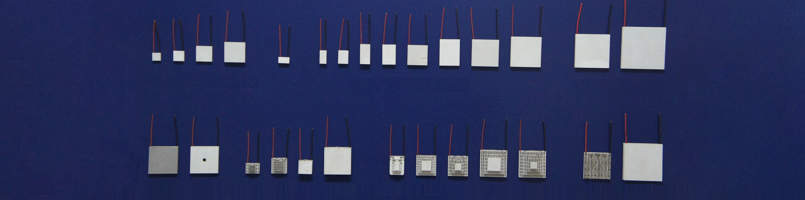
Number of stages (Stages):
This is the most distinctive feature of multi-stage thermoelectric modules, peltier elements. Commonly, there are 2 stages, 3 stages, or even 6 stages thermoelectric cooling module.
Rule of thumb: The more stages, the larger the temperature difference that can be achieved, but the cooling capacity (Qc) will be smaller and the price will be higher. Generally, the maximum temperature difference of a single-stage is approximately 60-70°C. If a temperature of -80°C or lower is required, a multi-stage peltier module must be selected.
Maximum cooling capacity (Qmax):
Refers to the maximum heat absorption capacity when the temperature difference is 0.
Selection suggestion: The actual cooling capacity (Qc) during operation is much smaller than Qmax. It is generally recommended that Qmax should be 1.3 to 2 times your actual heat load, leaving a margin to ensure efficiency and lifespan.
Maximum temperature difference (ΔTmax):
Refers to the ultimate temperature difference that the thermoelectric cooling module,peltier element can achieve (when the cooling capacity is 0).
Selection suggestion: The ΔTmax selected should be 10-20% higher than the actual temperature difference you need.
Voltage and current (Vmax / Imax):
The internal resistance of multi-stage thermoelectric cooling module, TEC module is usually large, and the voltage may be high (such as 24V, 48V, or even higher), while the current is relatively small. Make sure your power supply can drive it.
Step 3: Utilize the performance curve (precise matching)
This is the most crucial step. Do not merely rely on the maximum values stated in the specification sheet!
The performance of multi-stage thermoelectric cooling module thermoelectric module is nonlinear.
Determine the operating point: On your target temperature difference (ΔT) and target cooling capacity (Qc), refer to the curve graph.
Find the optimal current (Iop): Locate the corresponding current value.
Calculate the energy efficiency ratio (COP): Try to make the thermoelectric module operate in the region with a higher COP (usually around 30%-50% of the maximum current), rather than running at full capacity. Running at full capacity may provide faster cooling, but it generates excessive heat and has extremely low efficiency.
Step 4: Structure and Installation
Multistage thermoelectric cooling modules (multi-stage TEC module) are more fragile than single-stage thermoelectric cooling modules(single stage peltier modules). When selecting the type, the physical structure must be taken into account:
Size Limitations:
Multistage peltier cooling modules are generally not recommended to be made too large (such as larger than 62x62mm), as an overly large area can easily cause the ceramic plates to warp or break. For large-plane cooling, it is recommended to use multiple small-sized peltier mdoules connected in parallel or series.
Connection method:
Series connection: Recommended. The current is consistent, easy to control. If one piece is damaged, it can be easily detected (by a break in the circuit).
Parallel connection: Not recommended. If the internal resistance of one piece changes, the current distribution will be uneven, leading to the “current competition” phenomenon, accelerating damage.
Post time: May-19-2026


